For more information and discussion, please go and visit the buyer forum https://forum.avhzy.com/
ユーザープレーヤーフォーラムを訪問して多くのサーポートを取得できます。リンク: https://forum.avhzy.com/
Note:
1. Be careful of the high temperature of the radiator when it is working.
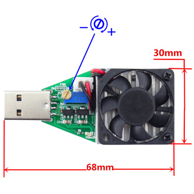
2. Increase the current: rotate the yellow button clockwise; Decrease the current: rotate the yellow button anti-clockwise.
Cable Resistance & Electronic Load:
Since the attached electronic load has a relatively large
temperature coefficient, when doing a A-C cable
resistance test, please adjust the load to a relatively lower
value (0.6A-1A) to reduce the influence of the temperature
variation generated by the load itself.
Parameters:
Applied voltage range: DC 3.7V-13V
Adjustable current range: 0.15A-3.00A
Electricity discharging: continuous 15W
Radiator Operation Temperature: above 40 ℃
Should I connect 5v to PC micro USB port when doing a USB battery pack discharge test?
Are you trying to get the discharge curve of the battery pack or just want to see how much capacity and energy can it discharge? If you want to get the discharging graph, you can just use the offline recording feature, set a proper recording rate and run it, but it is obvious it will stop recording when the voltage drops below 4V (Minimum voltage when running without independent power source), you can use a common 5V independent power supply to the micro port to solve the problem. If you just want to see the capacity & energy the battery discharges, recording feature isn’t required, just see the capacity & energy accumulation data on the home screen.
You might want to mention to people that the fan might not be set to ‘on’ by default, and that they’ll have to jump the lead on the circuit board in order to turn it on. I almost got my soldering iron out to make that connection permanent.
By default, the fan will automatically turn on when the temperature on the board reaches 40C, so it’s nothing to worried about.
But if you want it always be on, you should solder the jump hole.
“they’ll have to jump the lead on the circuit board in order to turn it on”, I don’t know where you get this misunderstanding, could you please point out what confused you?
(I’m the developer but not the seller, I don’t know what exactly they said to you).
Thank you.